sRGB/ACEScg Luminance Comparison

Introduction

When I was searching information about rendering in different color spaces, I came across that using wider color primaries  (e.g. ACEScg instead of sRGB/Rec709) to perform lighting calculation will have a result closer to spectral rendering. But will this affect the brightness of the bounced light? So I decided to find it out. (The math is a bit lengthy, please feel free to skip to the result.)


Comparison method

To predict the brightness of the rendered image, we can consider the reflected light color after n bounces. To simplify the problem, we assume all the surfaces are diffuse material. We can derive a formula for the RGB color vector c after n light bounces.

To calculate lighting in different color spaces, we need to convert the albedo and initial light color to our desired color gamut by multiplying with a matrix M (For rendering in sRGB/Rec709, M is identity matrix).

Finally, we can calculate the luminance of the bounced light by computing the dot product between the color vector c and luminance vector Y of the color space (i.e. Y is the second row vector of the conversion matrix from a color space to XYZ space, with chromatic adaptation).

Now, we have an equation to compute the brightness of a reflected ray after n bounces in arbitrary color space.


Grey Material Test

To further simplify the problem, we assume all the surfaces are using the same material:

Then assuming all the surfaces are grey in color:

Now, the luminance equation is simpler to understand.

Substituting the matrix M and luminance vector Y for sRGB color gamut, the equation is very simple:

Then we do the same thing for ACEScg. Surprisingly, there are some constants roughly equal to one, so we can approximate them with constant one and the result will roughly equal to the luminance equation of sRGB.

As both equations are roughly equal, the rendered images in sRGB and ACEScg should be similar. Let's try to render images in sRGB and ACEScg to see the result (images are path traced with sRGB and ACEScg primaries, and then displayed in sRGB).

Path traced in sRGB
Path traced in ACEScg

Both images looks very similar! So rendering in different color spaces with grey material will not change the brightness of the image. At least, the difference is very small after tone mapped to a displayable range.


Red Material Test

Now, let's try to use red material instead of grey material to see how the luminance changes (where k is a variable to control how 'red' the material is):

But the equation is still a bit complex,  so we further assume the initial light color is white in color.

Then we perform the same steps in last section, substituting M and Y into luminance equation.
sRGB luminance equation


ACEScg luminance equation

Unfortunately, both equations are a bit too complex to compare, having 2 variables k and n... May be let's try to plot some graphs to see how those variables affect the luminance, with number of bounced light = 3 and 5 (i.e. n=3 and n=5, skipping the N dot L part because both equations have such term). From the graphs below: when k increases (i.e. the red color is getting more saturated, with RGB value closer to (1, 0, 0) ), luminance difference will increase, hence sRGB will have a larger luminance value than ACEScg.


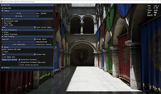
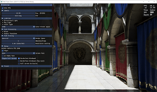
Then comparing the images rendered in sRGB and ACEScg:

Path traced in sRGB
Path traced in ACEScg

The indirectly lit area looks much brighter when rendered in sRGB. This makes sense because for any red color, its red channel value will be closer to one (while green/blue values will be closer to 0) when represented in sRGB compared to be represented in ACEScg. After several multiplication, the reflected light value should be larger when computation is done in sRGB.


RGB Material Test

How about using different colored material this time? Assuming 1/3 of the light bounced on surface that is red material, 1/3 is green material, and 1/3 is blue material. 

Like previous 2 sections, substituting M and Y, the luminance equation becomes:

sRGB luminance equation ACEScg luminance equation
 
And then plotting graphs to see how k and n varies:

The result is different this time. The sRGB luminance is smaller than ACEScg luminance, and the difference increases when both k and n increases. So the bounced light will be darker when rendered in sRGB.

Let's try rendering some images to see whether this is true. Although we cannot force the ray to bounce with 1/3 red/green/blue material exactly, I roughly assigned 1/3 of the material in red/green/blue color in the scene.

Path traced in sRGB
Path traced in ACEScg

From the screen shots above, the indirectly lit red material looks darker when rendered in sRGB (especially the curtains on the ground floor), while the differences for the blue and green material are small. We can think of the result like previous section, for a given red color, when it is represented in sRGB, its red channel value is closer to one, however, its blue and green channels values are closer to 0 compared to be represented in ACEScg (same for both blue and green material). So after several multiplication with different color material, the RGB values in sRGB may becomes closer to 0 because different color material cancel out each other (e.g. when light bounced on red and green albedo surface (1, 0, 0) , (0, 1, 0) in sRGB, the reflected light will be zero, while the same color represented in ACEScg, the color will not be "zeroed out"), resulting in darker image.


Conclusion

After testing with different assumptions, the brightness of images when rendered in sRGB can be darker, roughly equal or brighter than rendered in ACEScg. The brightness difference depends on material used in the scene. If the scene uses grey material only, brightness will be equal. If material has similar color (e.g. all red material), sRGB image will be brighter. If the scene has more color variation, the sRGB image may becomes darker. And turns out this conclusion can be arrived without doing such lengthy math. We can think of the same color value represented in sRGB and ACEScg space: Is the RGB value closer to 0 or 1 when represented in the color space? Will the RGB values 'cancel' each other when performing lighting calculation in the color space? So I was too stupid to figure out this simple answer early and instead worked on such lengthy math... >.<


Reference

[1] https://chrisbrejon.com/cg-cinematography/chapter-1-5-academy-color-encoding-system-aces/


Spectral Path Tracer

Introduction
Before starting this post, I would like to talk a bit about my homeland, Hong Kong. The Chinese government enacted a new National Security Law, bypassing our local legislative council. We can only read the full text of this law after it is enacted (with official English version published 3 days after that). This law destroys our legal system completely, the government can appoint judges they like (Article 44), jury can be removed from trial (Article 46), and without media and public presence (Article 41). This law is so vague that the government can prosecute anyone they don't like. People were arrested due to processing anti-government stickers. We don't even have the right to hate the government (Article 29.5). If I promote "Boycott Chinese Products", I may broke this law already... Also the personnel of the security office do not need to obey HK law (Article 60). This law even applies to foreigners outside HK (Article 38). Our voting right is also deteriorating, more pro-democracy candidates can be disqualified by this law in the upcoming election (Article 35)... So, if you are living in a democratic country, please cast a vote if you can.

Back to the topic of spectral path tracer. Path tracing in the spectral domain has be added in my toy renderer (along side with tracing in sRGB / ACEScg space). Spectral path tracer trace rays with actual wavelength of light instead of RGB channels. The result is physically correct, and some of the effect can only be calculated by spectral rendering (e.g. dispersion, iridescence). Although my toy spectral path tracer does not support such material, I would like to investigate how spectral rendering affects the bounced light color compared to image rendered with RGB color spaces. The demo can be downloaded here.
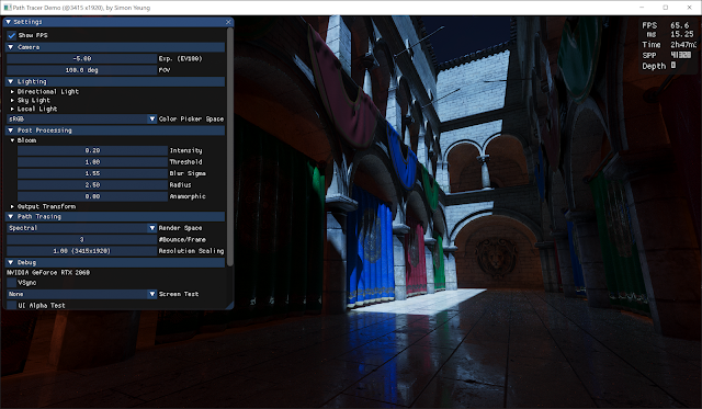
Spectral rendered image

Render Loop Modification
Referencing my previous DXR Path Tracer post, only a few modification need to be done to support spectral path tracing:
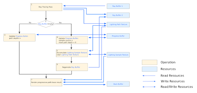
RGB path tracer render loop in previous post
When start tracing new rays, a wavelength is randomly picked. My first implementation uses hero wavelength with 3 wavelength samples per ray. The number 3 is chosen because it is convenient to replace existing code where rays are traced with RGB channels. So the "Light Path Texture" in previous post is modified to accumulate the energy at that 3 wavelengths during ray traversal. Finally, when the ray is terminated, the resulting energy in the "Light Path Texture" will be integrated with the CIE XYZ color matching function and stored in the "Lighting Sample Texture" in XYZ space, which later will be converted to the display device space (e.g. sRGB/AdobeRGB/Rec2020) as described in previous post.

Spectral Up Sampling Texture
One of the problem in spectral rendering is to convert texture from color to spectral power distribution(SPD), this process is called spectral up sampling. Luckily, there are many paper talks about it. The technique called "Spectral Primary Decomposition for Rendering with sRGB Reflectance" is used in the demo to up sample texture. I choose this method because of its simplicity. This method can reconstruct the spectrum by using linear combination of the texture color with 3 pre-computed spectral basis function:
But one thing bothered me is that, the meaning of texture color is a bit different than the spectral up sampling method. In PBR rendering, texture color is referring to albedo (i.e. ratio of radiosity to the irradiance received by a surface.), which is independent of CIE XYZ observer. While the up-sampling method is trying to minimize the least squares problem of the texture color viewed under illuminant D65 with CIE standard observer. May be the RGB albedo values are computed with SPD and XYZ observer function? I have no idea about it and may investigate about this in the future.

Spectral Up Sampling Light Color and Intensity
Beside spectral up sampling the texture, light also need to be up sampled. Because the light color can be specified in wide color in the demo, the up sampling method used in above section is not enough. The method "A Low-Dimensional Function Space for Efficient Spectral Upsampling" is used to up sample the light color. This method compute 3 coefficients using light color (i.e. from RGB to c0, c1, c2), and then the spectral power distribution, f (λ), can be computed as below:
Since, light is specified by color and intensity, after calculating the SPD coefficients, we need to scale the SPD curve, so that when integrating the scaled SPD with the CIE standard observer ȳ(λ) curve, the result should equals to the specified luminance intensity :
The scaling factor K is calculated numerically using Trapezoidal rule with 1nm wavelength interval and the ȳ(λ) curve is approximated with "multi-lobe approximation in "Simple Analytic Approximations to the CIE XYZColor Matching Functions". So, the light spectral power distribution is specified by 4 floating point numbers: 3 coefficients + 1 intensity scale.

In the demo, the original light intensity of RGB path tracer is modified so that it better matches the intensity of the spectral rendered image. Before the modification, the RGB lighting is done by simply multiplying the light color with light intensity. But now, this value is also divided by the luminance of the color (but this lose some control in the color picker UI...).
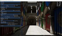
RGB light color multiply with
intensity only
RGB light color multiply with intensity
divided by color luminance
Spectral light with scaled SPD curve


In addition to the luminance scale, we also need to chromatic adapt the light color from illuminant E to illuminant D65/D60 before computing the 3 SPD coefficients, because the coefficients are fitted using illuminant E. If not doing this, the image will have a reddish appearance.
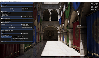
Computing light SPD coefficients without chromatic adaption
Computing light SPD coefficients with chromatic adaption

Importance Sampling Wavelength
As mention at the start of the post, the wavelengths are sampled using hero wavelength, which randomly pick 1 wavelength within the visible spectrum (i.e. 380-780nm in the demo), and then 2 additional samples are picked, which evenly separated within visible wavelength range. With this approach, there is a high variance in color. Sometimes with 100 samples per pixel, the color converge to the final color, but more often, it requires > 1000 samples per pixel to converge. It really depends on luck...
3 different spectral rendered images with hero wavelength using 100 samples per pixel,
The color looks a bit different between all 3 images with a noticeable red tint in the middle image.

To make the render converge faster, let's consider the CIE XYZ standard observer curves below, those samples with wavelength >650nm and <420nm will only have a few influence on the output image. So I tried to place more samples around the center of visible wavelength range.
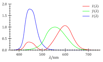
CIE 1931 Color Matching Function from Wikipedia
My first failed attempt is to use a cos weighted PDF curve like this to randomly pick 3 wavelengths for each ray:

A normalization constant is computed so that the PDF is integrated to one, and then CDF can be computed. To pick a random sample from this PDF, inverse method can be used. To simplify the calculation, the PDF is centered at 0 with width 200 instead of [380, 780] range. After sampling λ from the inverse of CDF, the λ is shifted by 580 to make it lies in [380, 780] range. To find the inverse of CDF:
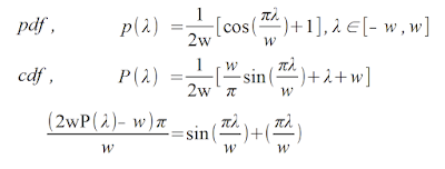
Compute inverse CDF of the cos weighted PDF (with w=200)

Unfortunately, this cannot be inverted analytically as mentioned here. So Newton's method(with 15 iterations,) is used as suggested from this post, which have the follow result:

3 different spectral rendered images with cos-weighted PDF using 100 samples per pixel,
The color still looks a bit different between all 3 images...

Sadly, the result is not improved, which gives more color variance than the hero wavelength method...

So I google for a while and found another paper: "An Improved Technique for Full Spectral Rendering". It suggests to use the cosh function for PDF, which its CDF can be inverted analytically:
The paper only suggest to use that PDF curve with center B= 538nm and A= 0.0072. Since this shape is similar to my cos weighted PDF, the color converge rate is similar (so I just skip capturing screen shots for this case)... But what if we use this curve with their center lying around the peak of the XYZ standard observer curve? To find this out, I tried to find the normalization constant within range [380, 780]nm, and then compute the CDF and inverse CDF:
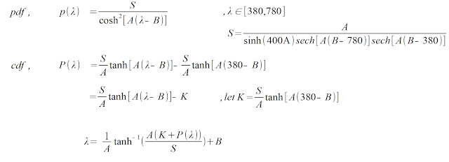


By using 3 different PDF to sample the wavelengths (A0=0.0078, B0= 600, A1= 0.0072, B1= 535, A2= 0.0062, B2= 445 are used in the demo), the image converge much faster than using hero wavelength. Using about 100 SPP will often enough to get a similar color to the converged image.
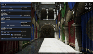
Rendered with 3 different cosh-curves PDF using 100SPP
Converged spectral rendered image.

Another problem with the color variance in hero wavelength is the camera movement. Since my demo is an interactive path tracer, when the camera moves, the path tracer re-generate a wavelength sample which change the color greatly every frame:
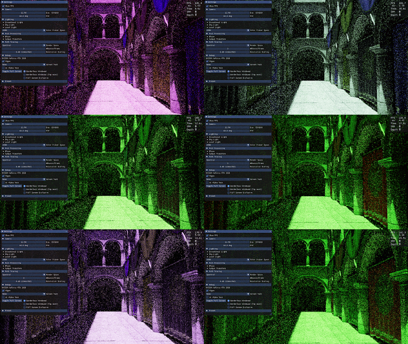
Camera movement with hero wavelength sampling

To give a better preview of color during first few samples of the path tracing. The random numbers are stratified into 9 regions so that the first ray will pick 3 random wavelengths lying around 600nm, 535nm and 445nm when substituted into the inverse CDF of cosh weighted curves, which will give some Red, Green, Blue color.

Code to generate stratified random numbers P0, P1, P2 within [0, 1] range.

With this stratified random number, color variation is reduced during camera movement:
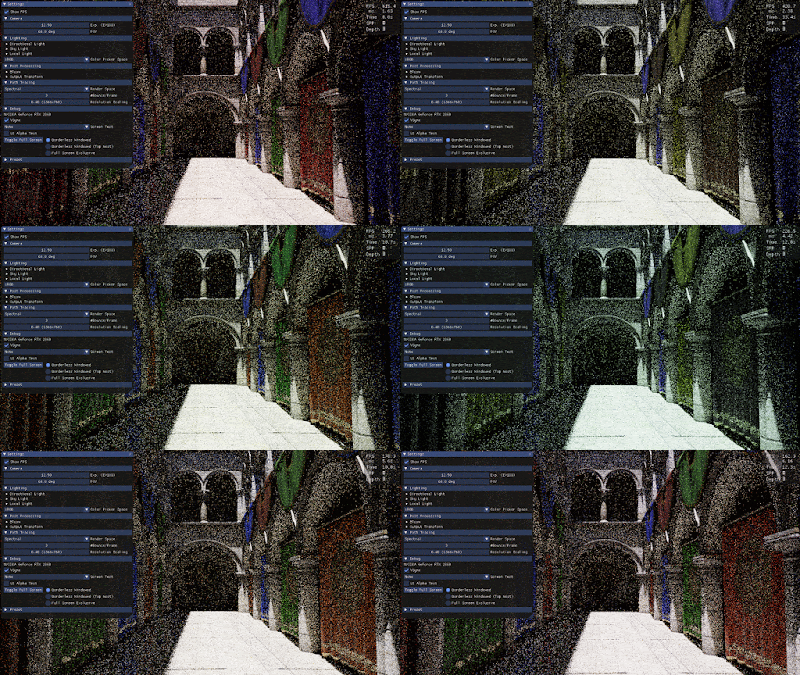
Camera movement with stratified random numbers.

Conclusion
In this post, I have described how a basic spectral path tracer can be implemented. The spectral rendered image is a bit different from the RGB rendered image (The RGB rendered image is a bit more reddish compared to the spectral traced one.). This may be due to the spectral up sampling method used, or not using a D65 light source. However, the bounced light intensity is not much different between tracing in Spectral and ACEScg space. In the future I would like to try using different light source such as illuminant E/D/F to see how it affects the color. I would also like to have a technique to spectral up sampling albedo with wide color gamut instead of sRGB color only.

References
[1] https://cgg.mff.cuni.cz/~wilkie/Website/EGSR_14_files/WNDWH14HWSS.pdf
[2] https://en.wikipedia.org/wiki/CIE_1931_color_space
[3] https://graphics.geometrian.com/research/spectral-primaries.html
[4] https://rgl.s3.eu-central-1.amazonaws.com/media/papers/Jakob2019Spectral_3.pdf
[5] http://jcgt.org/published/0002/02/01/paper.pdf
[6] https://www.researchgate.net/publication/228938842_An_Improved_Technique_for_Full_Spectral_Rendering


HDR Display

Introduction
Continue with the DXR Path Tracer in the last post, I updated the demo to support HDR display. It also has various small features updated such as adding per monitor high DPI support, path trace resolution scale (e.g. path trace at 1080, and bilinear upscale to 4K.) and added dithering to tone mapped output to reduce color banding (Integer back buffer format only). The updated demo can be downloaded here.
A photo of my HDR TV to show the difference between SDR and HDR

HDR Color Spaces
There are 2 swapchain formats/color spaces can be chosen to output HDR images on HDR capable monitor/TV:
1. Rec 2020 color space (DXGI_FORMAT_R10G10B10A2_UNORM + DXGI_COLOR_SPACE_RGB_FULL_G2084_NONE_P2020)
2. scRGB color space (DXGI_FORMAT_R16G16B16A16_FLOAT + DXGI_COLOR_SPACE_RGB_FULL_G10_NONE_P709)
Rec2020 color space is the common HDR10 format with PQ EOTF. But it is recommended to use scRGB color space on Windows. scRGB use the same color primaries at Rec709, which support wide color using negative values. I was confused about using negative values to represent a color (as well as intensity) at first. Because color gamut is usually displayed as CIE xy chromaticity diagram, I used to think of a given RGB value as a color interpolated inside the Red/Green/Blue gamut triangle using the barycentric coordinates. 
A debug chromaticity diagram showing Rec2020 color gamut.
Using a HDR backbuffer will show less clipped color
Although, it makes sense to represent a wide color using negative numbers using barycentric interpolation, I was confused how it to represent the intensity at the same time. It is because the chromaticity diagram skipped the luminance information. So, instead of thinking color inside the horseshoe-shaped diagram, it is easier for me to think about the color in 3D XYZ color space. The Red/Green/Blue color primaries of a gamut is 3 basis vectors in the XYZ color space. A linear combination of RGB values with the color primaries basis vectors can represent a color and intensity. Thinking in this way make me feel more comfortable. So the path traced lighting values are fed into ACES HDR tone mapper, transformed into Rec709 color space, and then divided by 80 when using scRGB color space(scRGB requires value of 1 to represent 80 nit).

HDR10 metadata
I have also played around with HDR10 metadata to see how it affects the image. But most of the data does not affect the image on my Samsung UA49MU7300JXKZ TV. The only data have effects on the image is "Max Mastering Luminance" which can affect the image brightness. Setting it to a small value will make image darker despite outputting a very bright 1000 nit image. Also, the HDR10 metadata only works in Full Screen Exclusive mode, or borderless windowed mode with HWND_TOPMOST Z order (I guess is the full screen optimization get enabled), using borderless window with HWND_TOP Z order won't work (but this mode is easier to alt-tab on single monitor set up...). Besides, entering Full Screen Exclusive mode may fail when calling SetFullscreenState() if the display is not connected to the adapter that used for rendering. I didn't notice this until I started to work on laptop which use the RTX graphics card for ray tracing and the laptop monitor is connected to the Intel graphics card. Looks like some hard work need be done in order to support Full Screen Exclusive mode properly (e.g. create a D3D Device/Command Queue/Swapchain and for the Intel graphics card and copy the ray traced image from the RTX graphics to Intel graphics card for full screen swapchain). But unfortunately, my demo does not support multi-adapter, so the HDR10 metadata may not work on such setup (I am outputting to the external HDR TV using the RTX graphics card, so that doesn't create a much problem for me...)...

Capability of my HDR TV
UI showing all the adjustable HDR10 meta in the demo

UI
Blending SDR UI with HDR image is handled in 2 steps: blend color and then brightness. All the UI is rendered into an off screen buffer (in 8 bit Rec709 color space). And then later blended with the ACES tone mapped image. Take a look at the ACES tone mapping function snippet below, the lighting value will be mapped to a normalized range in AP1 color space as an intermediate step (red part in the below code snippet). So in the demo, the UI in off screen buffer will be converted to AP1 color space and then blend with the tone mapped image at this step. (I have also tried blending in XYZ space and the result is similar in the demo.)

ACES tone map function snippet

Then the UI blended image can be transformed into target color space (e.g. scRGB or Rec2020, purple part in the above code snippet). When converting the normalized color data to HDR data, the ACES tone mapper interpolates the RGB values between Y_MIN and Y_MAX (i.e. blue part in the above code snippet). During this brightness interpolation, the demo adjust Y_MAX (e.g. 1000 to 4000 nits) to user defined UI brightness (e.g. 80 to 300 nits) depending on the UI alpha, using the following formula:


In the demo, BlendPow is set to 5 as default value. Although the result is not perfect (e.g. the UI alpha value may not looks blending linearly, depending on background luminance), it works well enough to avoid bleeding though from a bright background with UI alpha > 0.5:

Background Luminance: 0-10 nit
Background Luminance: 2 - 250 nit
Background Luminance: 1000 nit
Photos showing UI blending with HDR background, from dark to bright.

However, the above blending formula have artifact when Y_MAX is smaller than the UI brightness (But this may not happens and only happens in some debug view mode). In this case, the background may looks too bright after blending with the UI. To fix this, inverting the BlendPow may helps to minimize the artifact:


The below is an extreme example showing the artifact with Y_MAX set to 1 nit and UI set to 80 nit:
Without the fix, the artifact is very noticeable at the upper right corner
With the fix, the background is darkened properly
Looking back to the blue part of the ACES tone mapping function in the above code snippet, I was wondering will the image looks different as the Y_MIN and Y_MAX values are interpolated in the display color space (e.g. will the image looks different when interpolating in scRGB / Rec2020). To compare whether these 2 color are the same, we need to have both color in the same space. So let's convert the interpolated RGB value back to XYZ space:


So, interpolating in different display color space do have some differences as long as Y_MIN != 0. But The ACES tone mapper which defaults to use the STRECH_BLACK option which effectively setting Y_MIN= 0, so there should be no difference when interpolating values in difference color space. Out of curiosity, I have tried to disable the STRECH_BLACK option to see whether the image will look different when switching between the scRGB and Rec2020 back buffer with Y_MIN > 0, but the images still looks the same with a large Y_MIN... I am not sure why this happens, may be the difference is too small to be noticeable... In the demo, I take this into account and treat the Y_MIN as a value in the XYZ color space and interpolate the value like this:


Debug View Mode
To help debugging, several debug view modes are added. A "Luminance Range" view mode is used to display the luminance value of a pixel before tone mapping (ie. the physical light luminance entering the virtual camera) and after tone mapping (i.e. the output light luminance the monitor should be displayed):
Showing pixel luminance before tone mapping.
Showing pixel luminance after tone mapping.

A "Gamut Clip Test" mode to high light pixel that fall outside Rec709 gamut, i.e. those color can only be viewed with a HDR display or wide color monitor (e.g. AdobeRGB / P3 monitor).
Highlight clipped pixel with cyan color
A "SDR HDR Split" mode to compare the SDR/HDR images. But this mode can only be a rough preview of how SDR will look like on HDR back buffer. It is because SDR images are usually displayed brighter than 80 nit, the SDR part need to be brighten up (say to 100-200 nit) to make it look similar to using a real SDR back buffer. Also, in this view mode, because the HDR back buffer expect a pixel value in nit (either linear or PQ encoded), I don't apply any gamma curve to the SDR portion of the image, which may also result in differences to a real SDR version too.
A photo showing both SDR and HDR at the same time.
Bloom is exaggerated to show the clipped color in SDR
Conclusion
In this post, I have talked about the color spaces used for outputting to HDR display. No matter which color space format is used (e.g. scRGB/ Rec2020), the displayed image should be identical if transformed correctly (except some precision difference). Also, I have tried to play around with the HDR10 metadata, but most of the metadata does not change the image on my TV... I guess how the metadata is interpreted is device dependent. Lastly, SDR UI is composited with the HDR image by first blending with the color and then brightness. A simple blending formula is enough for the demo. A complicated algorithm can be explored in the future, say brighten up the UI depending on the brightness of a blurred HDR background (e.g. may be storing the background luminance in the alpha channel and blur it together with bloom pass?). A demo can be downloaded here to test on your HDR display (Some of the options are hid if not connecting to HDR display).

References
[1] https://channel9.msdn.com/Events/Build/2017/P4061
[2]  https://www.pyromuffin.com/2018/07/how-to-render-to-hdr-displays-on.html
[3] https://www.gdcvault.com/play/1024803/Advances-in-the-HDR-Ecosystem
[4] https://www.gdcvault.com/play/1026443/Not-So-Little-Light-Bringing
[5] https://developer.nvidia.com/implementing-hdr-rise-tomb-raider
[6] https://www.asawicki.info/news_1703_programming_hdr_monitor_support_in_direct3d
[7] https://onedrive.live.com/?authkey=%21AFU3moSbUzyUgaE&cid=A4B88088C01D9E9A&id=A4B88088C01D9E9A%21170&parId=A4B88088C01D9E9A%21106&o=OneUp
[8] https://www.shadertoy.com/view/4tV3WW