Can't believe it has been half a year since my last DXR AO post. It was a hard time in Hong Kong last year, but thanks to the social unrest and medical worker's strike, the Wuhan Coronavirus does not spread widely in the local community (but still have new cases everyday...). Due to the virus, it is better to stay at home, so I continue to code my path tracer. This new path tracer is unbiased by terminating rays with Russian Roulette. During path tracing, physical light unit are used. Also, rendering can be done in wide color space. Finally, the path traced result is tone mapped and output to sRGB/wide color gamut depends on the display device. A demo can be downloaded here (Please use latest graphics driver to run as I have encountered device remove hang on my laptop RTX2060 with old driver, but not on my desktop GTX1060... If the crash/hang still happens, please let me know. Thank you.).
 |
| Path Traced Sponza scene. |
Render Loop
At the start of the demo (or after any camera movement/lighting changes), a structured buffer, Ray Buffer, is initialized with 1 ray per pixel using the camera transform.
 |
| The struct stored in Ray Buffer, not tightly packed for easier understanding. |
Then a ray generation shader is dispatched to read the Ray Buffer and trace rays into the scene. Lighting is calculated and generate new Ray Buffer elements if the rays are not terminated and continue the path tracing in the next frame. Below is a simplified flow of the rendering operation executed every frame (with render passes on the left and resources on the right):
 |
| A simplified path tracing flow executed every frame |
- Ray Buffers are structured buffers storing the RayData struct. A ray will be traced for each element and if the ray is not terminated by Russian Roulette, it will be stored back to the Ray Buffer for the next frame.
- Lighting Path Texture is used for accumulating the lighting result when a ray is traversing along the path from the camera. It can be think of an intermediate result because the path is not fully traversed within a single frame, but across several frames.
- Progress Buffer is a 8 bytes buffer, with 4 bytes storing the current path depth and other 4 bytes storing the total accumulated sample count.
- Lighting Sample Texture is used for accumulating the lighting result of all the terminated rays (i.e. accumulating all the terminated ray result from Lighting Path Texture).
- Ray Tracing Pass dispatch a ray generation shader, sampling the Ray Buffer according to the DispatchRaysIndex() and then calling TraceRay() to calculate the lighting result inside the closest hit shader by randomly choosing diffuse or specular lighting (another shadow ray is traced towards light source during lighting calculation). The lighting result is added to Lighting Path Texture and non-terminated ray will be stored back into Ray Buffer for next frame.
- Checking whether all rays are terminated by using D3D12 predicate on the counter buffer of Ray Buffer (i.e. all rays terminated when counter == 0). Then different shader/operation will be executed depends on whether the Ray Buffer is empty.
- When there are still rays not terminated, increase the path depth in Progress Buffer.
- When all rays are terminated, increase the sample count and set path depth to 0 in Progress Buffer.
- Accumulate the current path lighting result in Lighting Path Texture to Lighting Sample Texture. Clear the Lighting Path Texture to 0 (it is cleared via compute shader instead of command list clear as the predicate does not work on the clear API, despite the spec say it would...)
- Regenerate the rays in Ray Buffer with 1 ray per pixel using the camera transform for path tracing new lighting samples in next few frames.
- Display the current lighting result to the back buffer.

|

|
| Path traced images | |
|---|---|
With the core operations described above, at most 2 rays per pixel can be launched to maintain an interactive frame rate on my GTX1060. On more powerful machines (i.e. RTX cards with hardware accelerated ray tracing), step 1 don't need to be terminated with the first closest hit, but bounce a few more times before storing back to the Ray Buffer (A "#Bounce/Frame" option is added to increase the number of bounce per frame for RTX cards).
 |
| Number of bounce per frame option to adjust performance |
ACES tone mapping
After calculating the HDR lighting value, we need to perform a tone map pass to map the lighting value to a displayable range. ACES tone mapping is chosen due to its popularity in recent years. ACES has a few tone mapping curves (they call it RRT + ODT) for different display with different color gamut and viewing condition. Some common display types are sRGB_100nit and Rec709_100nit. The input of RRT+ODT function expect RGB values in ACES2065-1 (AP0) gamut with a white point around(but not exact) D60. So we need to convert our lighting value (L_sRGB) to AP0 gamut by multiplying a few transformation matrices:
 |
| operation to convert RGB value from sRGB to AP0 |
So we just only need to select the appropriate ODT for the target display device. But unfortunately, not all common display gamut is provided, like my recently bought RTX laptop which comes with a 100% AdobeRGB color gamut monitor. ACES does not provide a suitable ODT to display the image in AdobeRGB color space. If using the common sRGB ODT, image will look too saturated. So I added a "Remap display color gamut" option in the demo:
 |
| Remapping option to display the path traced result according to display color primaies |
- Apply EOTF function to the ODT output to get linear lighting value.
- Transform the resulting RGB value in step 1 to the target display color gamut RGB value (e.g. AdobeRGB gamut on my laptop display), with Chromatic Adaption Transformation applied.
- Apply OETF function to the output of step 2 for display.
Also digging deeper in the ACES ODT source code, the 3 ODT used in the demo share many common code and only have different color space transform function / OETF at the end of ODT. In the future, I may refactor the RRT+ODT code and remove the remap display gamut function and directly transforn the ACES ODT output in XYZ space to the display gamut queried by IDXGIOutput6::GetDesc1() (or user selected gamut).
 |
| An ODT from ACES, the blue part is the same for all the 3 ODT used in the demo. The orange part is different depends on display, which can be replaced by display primaries returned from IDXGIOutput6::GetDesc1(), so the "Remap display color gamut" in the demo can be removed in the future. |
WCG rendering
Equipped with the knowledge of transforming between color spaces, I decide to try rendering in Wide Color Gamut instead. Games like GT Sport rendered in wide color already(Rec2020). Performing lighting calculation in wide color gamut can result in more accurate lighting than rendering in sRGB color space (despite displaying on sRGB monitor).

|

|

|
| Path Traced result rendered in different color space. Left:sRGB, Center:ACEScg, Right:Rec2020 | ||
|---|---|---|
In the demo, it can path trace in sRGB, ACEScg, Rec2020 color space. Inside the closest hit shader, albedo texture is read and transformed into the chosen rendering color space from sRGB. Also the light color is converted to chosen rendering color space and then multiply with the intensity. Finally inside the tone mapping pass, the result of lighting calculation is transformed to AP0 color space and feed into ACES RRT+ODT for display. You may notice some difference between rendering in sRGB and wide color gamut (e.g. ACEScg and Rec2020). If you have a wide color gamut monitor (e.g. AdobeRGB or DCI-P3), you can try to use the Rec2020 ODT with the "Remap display color gamut" option on (described in last section). This can produce fewer color clamping and display more saturated color. But under normal lighting condition, the difference is not that much, we need to set up specific lighting such as using a local sphere light with saturated color, then those wide color can be displayed. I guess this is due to both albedo texture and light color are in sRGB space, content may need to be adjusted in order to take advantage of wide color display.
|
|
| Wide Color path traced image, saved with different profile. Left:saved with sRGB profile Right: saved with AdobeRGB profile. The right image shows more saturated color when viewed on a color managed browser with a wide color display (e.g. iPhone monitor), otherwise 2 images may look the same. | |
|---|---|
Also, please note that this kind of wide color support is different from Windows 10 HDR/WCG settings. On my laptop, Windows report No for both HDR and WCG, but it do have an AdobeRGB monitor and capable of displaying wide color, we just need to correctly transform the images using the monitor color gamut.
 |
| My laptop has an AdobeRGB monitor, but Windows 10 Display capabilities report No for WCG. |
ACES ODT blue light artifact
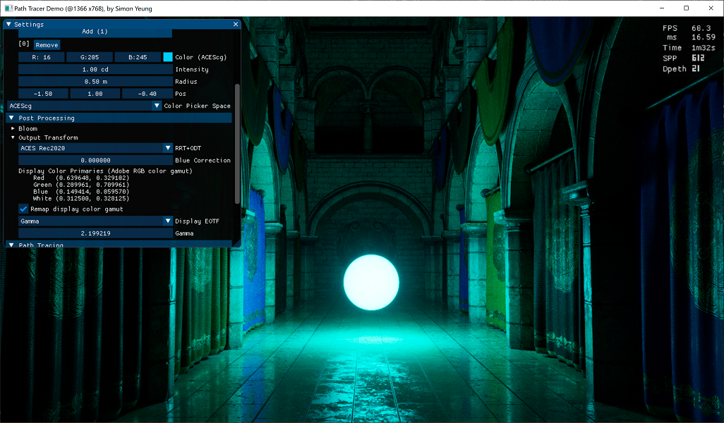
So far everything looks good when rendering in wide color space. Color get desaturated when they are over exposed. But it still has some issue when using a strong blue light...
 |
| Using a strong sRGB blue light will introduce hue shift... |
It is because pure blue (0, 0, 255) in sRGB space is not saturated enough when transformed to wide color gamut (e.g. ACEScg/Rec2020). Looking inside the ACES dev repo, it has a blue light artifact fix LMT to fix this issue. It works by de-saturating the blue color a bit to lessen the hue shift. So in the demo, I provided a "Blue Correction" parameter to adjust the blue de-saturation strength (As a side note, UE4 also use ACES tone mapper and comes with a blue correction parameter in post process setting).
 |
| desaturating blue color to fix the hue shift |
But I do like the saturated blue color, using the blue light artifact fix LMT will de-saturate the blue color made me sad. Below is the comparison between with/without the blue light LMT:

|

|
|
| Left: without blue light fix LMT, Right: with blue light fix LMT | ||
|---|---|---|
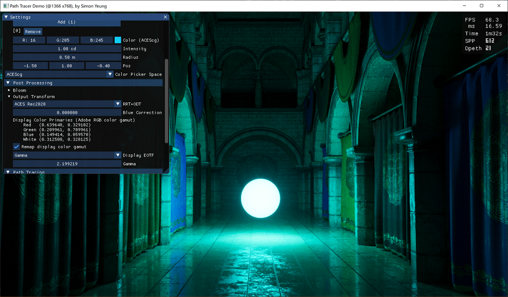
So may be we can work around the problem in the other way. Instead of making the blue color less saturated, we can make the light color more saturated. So I added a light "Color Picker Space" combo box to specify the color space of the picked RGB light value, so that more saturated blue light color can be chosen. By choosing an extremely saturated blue color (0, 0, 255) RGB value in ACEScg color space. We can get away with the purple color:
 |
| Using a saturated blue light in ACEScg space, without the blue light fix LMT |
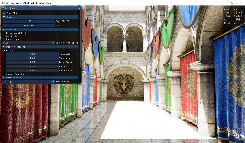
Bloom
Lastly, a bloom pass is added before tone mapping. Bloom pixels are extracted based on a threshold that exceeded the maximum luminance with the current exposure values. The maximum luminance is calculated with:
| max luminance calculated using EV100 |
 |
| Input image for the bloom pass |

|

|

|

|
| Left column: bloom in HSV space. Right column: bloom in RGB space. Upper row: Lighted scene combined with bloom. Lower row: Debug images showing only the bloom component. |
|
|---|---|
The bloom calculated using HSV space introduce less saturated color. The situation will be exaggerated when the image is over-exposed:
|

|

|
| Left:Bloom input image. Center:Bloom in HSV space. Right: Bloom in RGB space. |
||
|---|---|---|
In this post, the core algorithm of my DXR path tracer is described, together with some color space conversion. There are much more stuff to be done in the future like, support dynamic geometry during ray tracing, adding a denoiser for path traced output, implement hybrid rasterization/ray tracing rendering, spectral rendering to compute a ground truth reference. Also, this is my first time to write code about color space management. Currently, in the demo, the 3D lighting can be displayed correctly using the monitor gamut, but the UI is not managed properly. Also, 4K and HDR need to be supported too.
References
[1] https://seblagarde.files.wordpress.com/2015/07/course_notes_moving_frostbite_to_pbr_v32.pdf
[2] https://microsoft.github.io/DirectX-Specs/d3d/Raytracing.html#addressing-calculations-within-shader-tables
[2] https://github.com/ampas/aces-dev
[3] http://www.brucelindbloom.com/index.html?Eqn_RGB_XYZ_Matrix.html
[4] http://www.brucelindbloom.com/index.html?Eqn_ChromAdapt.html
[5] http://www.polyphony.co.jp/publications/sa2018/
沒有留言:
發佈留言