In recent years, there are more and more papers talking about applying physically based BRDF in games. So I decided to spend some time to investigate it. For a BRDF to be physically plausible, it should satisfy 2 conditions:
- Reciprocity: The incident light direction(l) and reflected light direction(r) for a BRDF(f) is the same after the incident and reflected direction is swapped. i.e. f(l, r)= f(r, l)
- Energy Conservation: The total energy of reflected light is less than or equal to the energy of the incident light. i.e.

A physically based specular BRDF is based on micro-facet theory, which describe a surface is composed of many micro-facets and each micro-facet will only reflect light in a single direction according to their normal(m):
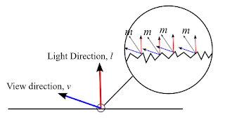 So, in the above diagram, for light coming from direction l to be reflected to viewing direction v, the micro-facet normal m must be equals to the half vector between l and v.
A micro-facet BRDF has the following form:
 which consists of 3 terms: Fresnel term(F), Distribution term(D) and Geometry term(G). Their meaning can be found in the background talk presented by Naty Hoffman in siggraph 2010. And these 3 terms can be chosen independently as stated in the talk Physically-based lighting in Call of Duty:Black Ops (although "Microfacet Models for Refraction through Rough Surfaces" states that some G depends on D to maintain energy conservation, but some G are extended to handle arbitrary distribution, so in this blog post, I assume that the G function is independent of D). So I decided to find some distribution functions D and geometry functions G and play with different combinations to see how it affects the rendering result. You can also play around with different combinations using the WebGL demo(need a webGL enabled browser such as Chrome) in the last section of the post.

A micro-facet BRDF has the following form:

Fresnel Term
In this test, I use the common Schlick approximation to the Fresnel equation:
 and f0 is found by using the following equation:
 where the refractive index n can be tuned in the demo.
Distribution Term
Distribution term is used to describe how the microfacet normal distributed around a given direction. In the demo, I used two distribution function: Blinn-Phong and Beckmann distribution function.
For Blinn-Phong distribution, we can derive the distribution function by satisfying the equation:
 which means that the projected microfacet area is equal to macro surface area for any projected direction v. So we choose v=n which simplify the equation:
 To derive the Blinn Phong distribution function from original Blinn Phong specular term, we just need to multiply a constant K to satisfy the equation:

While the Beckmann distribution has the following form:
 To convert between the roughness m in Beckmann distribution and shininess α in Blinn-Phong distribution, the following formula is used:
 which gives a very similar result when both refractive index n and roughness m are small. When n>10 and m>0.5 the 2 distribution start to show difference and the difference will get larger when both m and n are getter larger.

Geometry Term
Geometry term is used for describing how much the microfacet is blocked by other microfacet. In the demo, 4 geometry terms have been tested: implicit, Cook-Torrance, Schlick approximation to Smith's shadowing function and Walter approximation to Smith's shadowing function.
The first one is implicit geometry function which has the form:
 It is called implicit because when it is used, the microfacet BRDF will only depends on Fresnel equation and distribution function.
The second one used for testing is Cook-Torrance geometry function:
 And the other 2 geometry functions used are both trying to approximate the Smith's shadowing function which decompose the geometry function into another 2 geometry function as below:
 With Schlick's approximation, the following G1 is used:
 While Walter's approximate G1 as:
 Among 4 geometry terms, the implicit one always show a darker specular color. While the other 3 geometry functions have similar appearance when the roughness m is small. When m is getter larger, the Schlick function will slightly darker than the Cook-Torrance and Walter geometry function. Both Cook-Torrance and Walter function gives a very similar results:

Energy Conservation between Diffuse and Specular BRDF
Energy conservation is important for a physically based BRDF, but most paper only talks about the conservation within the specular BRDF. How about the energy conservation between the diffuse term and specular term? I can only find 2 ways to do this from the paper provided by Tri-Ace. They multiply the diffuse reflection term with a diffuse Fresnel term:
 And they later discovered that this term can be approximated with (1- f0), which will show very similar results. However, using this term will violate the reciprocity of the BRDF. If diffuse energy conservation is enabled, when the refractive index change, the ratio between the diffuse and specular reflection also change accordingly.

WebGL Demo
I provide a webGL program so that you can play around with the settings I described above. The model is illuminated by a single white directional light and the red color is the diffuse color. The diffuse BRDF is just a lambert surface which can be turned off in the demo. Dragging inside the viewport can rotate the camera. The source code can be downloaded from here.
Conclusion
Physically plausible BRDF can give a different material appearance for a surface compare to traditional lighting model. However, in this post, I only use 1 microfacet BRDF for all 3 RGB channels, using different BRDF settings for difference channels is also possible as some material like copper and gold have different f0 term in RGB channels. Also only direct lighting is investigated where secondary lighting BRDF will be left for future blog post.
Reference
[1] Background: Physically-Based Shading (Naty Hoffman): http://renderwonk.com/publications/s2010-shading-course/hoffman/s2010_physically_based_shading_hoffman_a_notes.pdf
[2] Practical Implementation of Physically-Based Shading Models at tri-Ace (Yoshiharu Gotanda): http://renderwonk.com/publications/s2010-shading-course/gotanda/course_note_practical_implementation_at_triace.pdf
[3] Crafting Physically Motivated Shading Models for Game Development (Naty Hoffman): http://renderwonk.com/publications/s2010-shading-course/hoffman/s2010_physically_based_shading_hoffman_b_notes.pdf
[4] Physically-based lighting in Call of Duty: Black Ops: http://advances.realtimerendering.com/s2011/Lazarov-Physically-Based-Lighting-in-Black-Ops%20(Siggraph%202011%20Advances%20in%20Real-Time%20Rendering%20Course).pptx
[5] Microfacet Models for Refraction through Rough Surfaces:http://www.cs.cornell.edu/~srm/publications/EGSR07-btdf.pdf
[6] http://www.rorydriscoll.com/2009/01/25/energy-conservation-in-games/
In this test, I use the common Schlick approximation to the Fresnel equation:
Distribution Term
Distribution term is used to describe how the microfacet normal distributed around a given direction. In the demo, I used two distribution function: Blinn-Phong and Beckmann distribution function.
For Blinn-Phong distribution, we can derive the distribution function by satisfying the equation:


While the Beckmann distribution has the following form:


Geometry Term
Geometry term is used for describing how much the microfacet is blocked by other microfacet. In the demo, 4 geometry terms have been tested: implicit, Cook-Torrance, Schlick approximation to Smith's shadowing function and Walter approximation to Smith's shadowing function.
The first one is implicit geometry function which has the form:
The second one used for testing is Cook-Torrance geometry function:


Energy Conservation between Diffuse and Specular BRDF
Energy conservation is important for a physically based BRDF, but most paper only talks about the conservation within the specular BRDF. How about the energy conservation between the diffuse term and specular term? I can only find 2 ways to do this from the paper provided by Tri-Ace. They multiply the diffuse reflection term with a diffuse Fresnel term:


WebGL Demo
I provide a webGL program so that you can play around with the settings I described above. The model is illuminated by a single white directional light and the red color is the diffuse color. The diffuse BRDF is just a lambert surface which can be turned off in the demo. Dragging inside the viewport can rotate the camera. The source code can be downloaded from here.
| Refractive Index, n (1.0 - 20.0) | (n= / Fresnel 0: ) | |
| Roughness, m (0.01- 1.0) | (m=) | |
| Render Diffuse | Rotate Model | |
Physically plausible BRDF can give a different material appearance for a surface compare to traditional lighting model. However, in this post, I only use 1 microfacet BRDF for all 3 RGB channels, using different BRDF settings for difference channels is also possible as some material like copper and gold have different f0 term in RGB channels. Also only direct lighting is investigated where secondary lighting BRDF will be left for future blog post.
Reference
[1] Background: Physically-Based Shading (Naty Hoffman): http://renderwonk.com/publications/s2010-shading-course/hoffman/s2010_physically_based_shading_hoffman_a_notes.pdf
[2] Practical Implementation of Physically-Based Shading Models at tri-Ace (Yoshiharu Gotanda): http://renderwonk.com/publications/s2010-shading-course/gotanda/course_note_practical_implementation_at_triace.pdf
[3] Crafting Physically Motivated Shading Models for Game Development (Naty Hoffman): http://renderwonk.com/publications/s2010-shading-course/hoffman/s2010_physically_based_shading_hoffman_b_notes.pdf
[4] Physically-based lighting in Call of Duty: Black Ops: http://advances.realtimerendering.com/s2011/Lazarov-Physically-Based-Lighting-in-Black-Ops%20(Siggraph%202011%20Advances%20in%20Real-Time%20Rendering%20Course).pptx
[5] Microfacet Models for Refraction through Rough Surfaces:http://www.cs.cornell.edu/~srm/publications/EGSR07-btdf.pdf
[6] http://www.rorydriscoll.com/2009/01/25/energy-conservation-in-games/
what will you deal with the (n.v) in the denominator of BRDF model? when the angle between two is 90 degree. It will be 0.
回覆刪除I havn't handle this case in the demo as those surface will not be seen(because no normal map is used). But you may reference the paper "Crafting a Next-Gen Material Pipeline for
刪除The Order: 1886" (http://blog.selfshadow.com/publications/s2013-shading-course/rad/s2013_pbs_rad_notes.pdf) which they handle this by not clamping the (n.v) to zero to have a smooth shading.
Simon, thanks for this educational piece! A question: for using normal maps, where would I have to remove the clamp-zero for NdotV? I'm using BlinnPhong distribution, no energy conservation, and "implicit" geometry term. I presume it's in the geometry term? Do I remove both clamps? Don't notice a big difference experimentally but I do notice the artifacts when using a normal map.. thanks in advance =)
刪除Hi Phi S, from the paper, removing clamp-zero for NdotV only applies to the Smith's shadowing function (i.e. G= G1(n, l)G1(n, v)), which doesn't affect "implicit" geometry term. Also by tracing the source code in the appendix A of the paper, the NdotV is computed as max(dot(n, v), 0.0001f) and then passed into G1(n, v) to avoid the division by zero artifacts.
刪除Thanks, good info ;)
刪除Are you sure it is correct that you are giving the fresnel function the halfVec? I think it should have the macro-surface normal instead, but I'm not quite sure (it's a bit confusing because for the microsurfaces, n = h, but that's not true for the macrosurface). If you change the shader so that you only see the fresnel:
回覆刪除gl_FragColor = vec4(1.0)*fresnel(u_fresnel0, halfVec, u_lightDir) + 0.00000000000000000000001*vec4(color_diff+color_spec, 1.0);
you'll see that it looks very weird with halfVec, but if you change it from halfVec to "normal", it looks more like what I think fresnel would look like.
Hi whoppix, from Siggraph 2013 PBS intro slides: "Recall that in a microfacet BRDF the relevant normal direction is the h vector (only the microfacets with normals aligned to h are visible). This means that we need to use the angle between v and h for Fresnel reflectance (or l and h - it’s the same angle)."
刪除Yeah, but I think they are talking about the microfacets there (for microfacets n = h), I don't know how it's supposed to be transferred to the macrosurface (after all, we only know the n and h vectors for the macrosurfaces, not for the microsurfaces)
刪除Have a look at these two renders, rendered with "output_color = fresnel;", where fresnel is the schlick approximation as described on the wikipedia page:
http://dl.dropboxusercontent.com/u/21559589/fresnel-a.png
http://dl.dropboxusercontent.com/u/21559589/fresnel-b.png
The first one (which looks somewhat plausible for being fresnel) is rendered with
vec4 fresnel = fresnel_schlick(v, n, c_spec);
whereas the second one (which seems to look nothing like fresnel) is rendered with
vec4 fresnel = fresnel_schlick(v, h, c_spec);
Nevermind, it seems that using the h vector is correct after all. It just looks implausible when plotted on its own, but when combined with shadowmasking and the ndf, it looks correct, whereas the one with the normal vector actually creates fresnel even when there should be none.
刪除Exactly -- we don't "know" the micro-surface in a way the bumpmap or the geometry tells us about the macro-surface, which is exactly what the various different interchangable/modular NDF (D) and shadow-mask/visibility (G) attempt to approximate. Once fully understood ---which sadly took me way too long--- it's a beautiful concept with beautiful results indeed ;)
刪除One thing that puzzles me with the NDF function is that it's supposed to be the ratio of "visible" microsurface to a given direction divided by the whole microsurface area (if I have understood correctly). So the value of the function D should never exceed 1, am I correct? Still, if you consider for example the blinn-phong NDF, if NdotH becomes 1 and you have high enough value for alpha, the NDF function will yield values that are greater than one. I'm having problems with my implementation where on certain angles the silhouettes of objects area completely white, and it's because my NDF function will be larger than one. I know I must have misunderstood something but I'm not sure what :(
回覆刪除nice blog
回覆刪除