Color Matching Function Comparison

Introduction

When performing spectral rendering, we need to use the Color Matching Function(CMF) to convert the spectral radiance to XYZ values, and then convert to RGB value for display. Different people have a slight variation when perceiving color, and age may also affect how color are perceived too. So the CIE defines several standard observers for an average person. The commonly used CMF are CIE 1931 2° Standard Observer and CIE 1964 10° Standard Observer. Beside these 2 CMF, there also exist other CMF such as Judd and Vos modified CIE 1931 2° CMF and CIE 2006 CMF. In this post, I will try to compare the images rendered with different CMF (as well as some analytical approximation). A demo can be downloaded here (the demo renders using wavelength between [380, 780]nm, which may introduce some error with CMF that have a larger range).

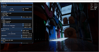
Left: rendered with CIE2006 CMF
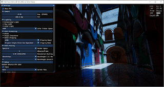
Right: rendered with CIE1931 CMF

CMF Luminance

When I was implementing different CMF into my renderer, replacing the CMF directly will result in slightly different brightness of the rendered images:

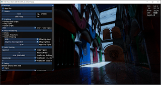
Rendered with 1931 CMF
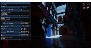
Rendered with 1964 CMF

This is because the renderer uses photometric units (e.g. lumen, lux..) to define the brightness of the light sources. Since the definition of luminous energy depends on the luminosity function (usually the y(λ) of CMF), we need to calculate the intensity of the light source with respect to the chosen CMF. Using the correct luminosity function, both rendered images have similar brightness:

Rendered with 1931 CMF
Rendered with 1964 CMF + luminance adjustment


CMF White Point

When using different CMF, the white point of different standard illuminant will be slightly different:

White point from wikipedia

Since we are dealing with game texture, color are usually defined in sRGB with a D65 white point, we need to find the white point of the D65 illuminant for the CMF that will be tested in this post. Unfortunately, I can't find D65 white point for the CIE 2006 CMF on the internet, so I calculated it myself (The calculation steps can be found in the Colab source code):

CIE 2006   2° : (0.313453, 0.330802) 

CIE 2006 10° : (0.313786, 0.331275)

But when I rendered some images with and without chromatic adaptation, the result looks similar:

1964 CMF without chromatic adaptation
1964 CMF with chromatic adaptation

So I searched on the internet, I can't find any information whether we need to chromatic adapt the rendered image due to different white point when using different CMF... May be this is because the difference is so small that applying chromatic adaptation makes no visible difference. 


CIE 2006 CMF analytical approximation

The popular CIE 1931 and 1964 CMF have simple analytical approximation, such as: "Simple Analytic Approximations to the CIE XYZ Color Matching Functions" (which will be tested in this post). The newer CIE 2006 CMF lacks such an approximation. So I derived one using similar methods and the curve fitting process can be found in the Colab source code.

2006 2° lobe approximation:

2006 2° lobe approximation shader source code
black lines: exact 2006 2° CMF
color lines: approximated 2006 2° CMF
 
2006 10° lobe approximation:

2006 10° lobe approximation shader source code
black lines: exact 2006 10° CMF
color lines: approximated 2006 10° CMF

Saturated lights comparison

With the above changes to the path tracer, we can render some images for comparison. A scene with several saturated lights using sRGB color (1,0,0), (1,1,0), (0,1,0), (0,1,1), (0,0,1), (1,0,1) is tested (which will be spectral up-sampled). 10 different CMF are used:

  • CIE 1931 2° 
  • CIE 1931 2° with Judd Vos adjustment
  • CIE 1931 2° single lobe analytic approximation
  • CIE 1931 2° multi lobe analytic approximation
  • CIE 1964 10° 
  • CIE 1964 10° single lobe analytic approximation
  • CIE 2006 2°
  • CIE 2006 2° lobe analytic approximation
  • CIE 2006 10°
  • CIE 2006 10° lobe analytic approximation

Here are the results:

CIE 1931 2°
CIE 1931 2° with Judd Vos adjustment
CIE 1931 2° single lobe analytic approximation
CIE 1931 2° multi lobe analytic approximation
CIE 1964 10°
CIE 1964 10° single lobe analytic approximation
CIE 2006 2°
CIE 2006 2° lobe analytic approximation
CIE 2006 10°
CIE 2006 10° lobe analytic approximation

From Wikipedia:

"The CIE 1931 CMF is known to underestimate the contribution of the shorter blue wavelengths."

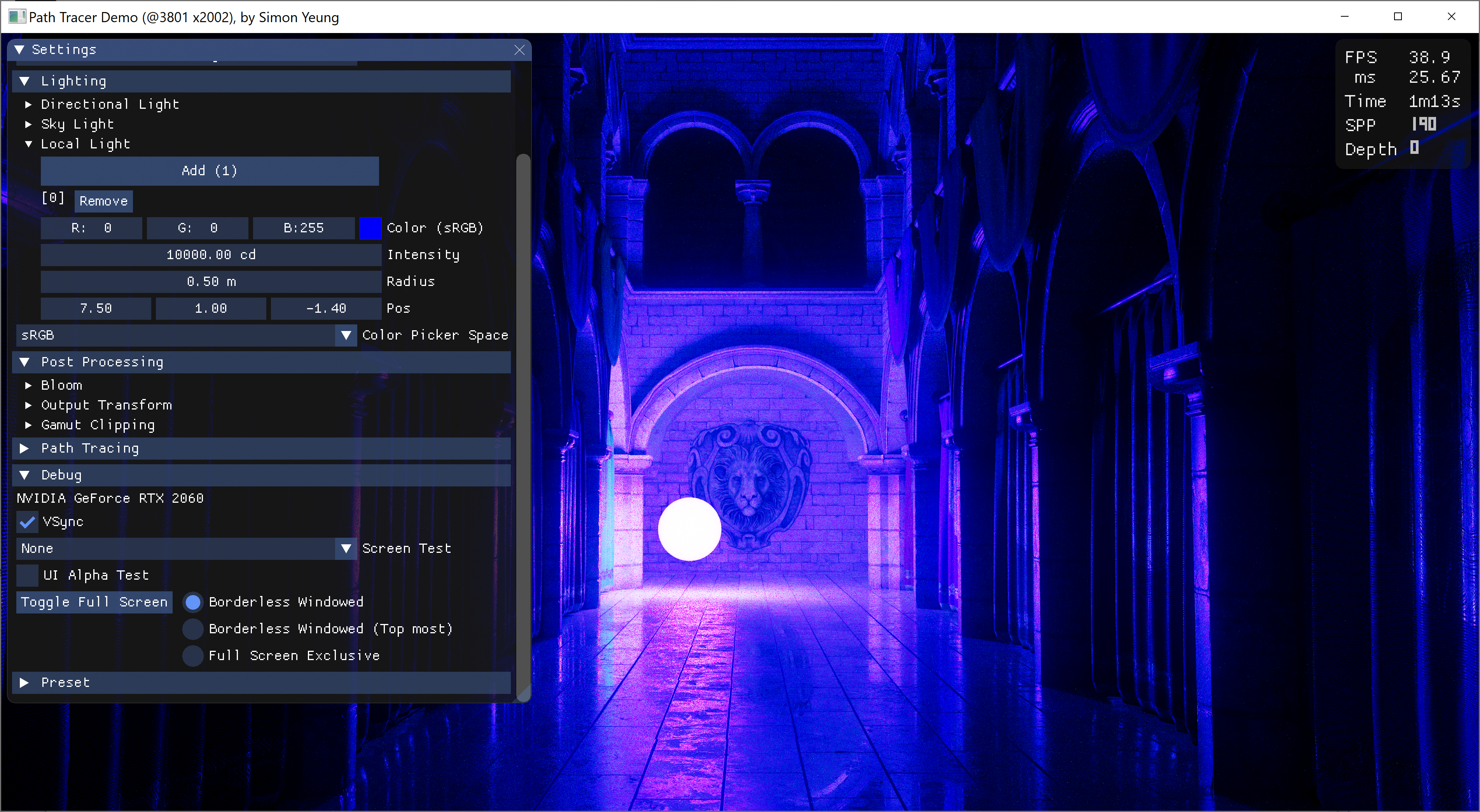
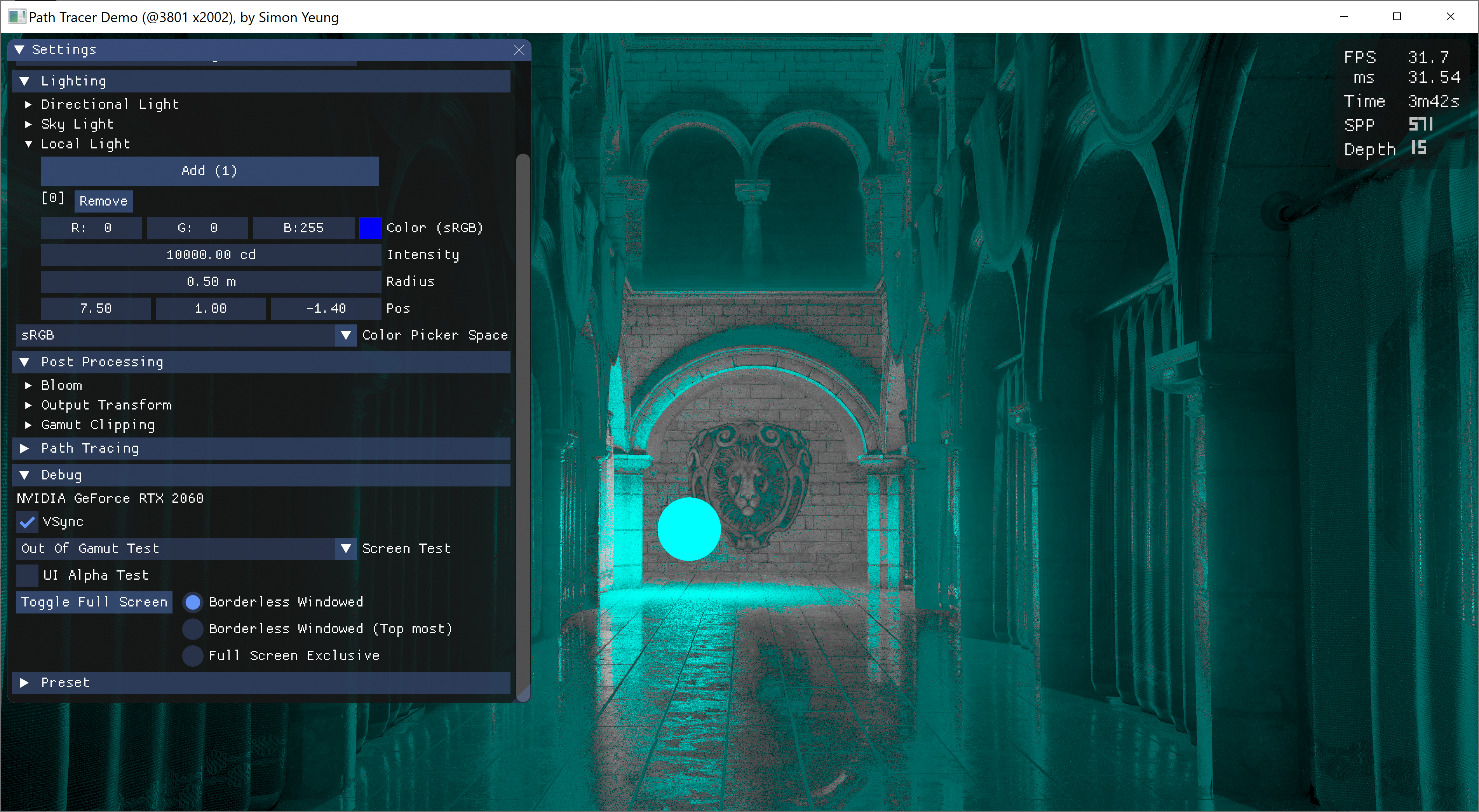
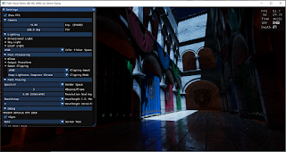
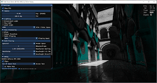
So I was expecting some variation for the blue color when using different CMF. But to my surprise, only the CIE 1931 CMF suffer from the “Blue Turns Purple” Problem (Edited: As pointed out by troy_s on twitter, the reference I provided was wrong, the link talks about psychophysical effect, while the current issue is mishandling of light data) which we have encountered in previous posts (i.e. saturated sRGB blue light will render purple color). Originally, after previous blog post, I was investigating this issue and was suspecting the ACES tone mapper cause the color shift (as this issue does not happen when rendering in narrow sRGB gamut with Reinhard tone mapper). I was thinking may be we can use the OKLab color space to get the hue value before tone mapping and tone map only the lightness to keep the blue color. But when I tried with this approach, the hue value obtained before tone mapping is still purple color, which suggest may not be the tone mapper causing the issue (or somehow my method of getting the hue value from HDR value is wrong...). So I have no idea on how to solve the issue and randomly toggle some debug view modes. Accidentally, I found that some of the purple color are actually inside my AdobeRGB monitor display gamut (but outside the sRGB gamut on another monitor...), so the problem is not only caused by out of gamut color producing the purple shift...

The purple color on the wall is within displayable Adobe RGB gamut
Highlighting out of gamut pixel with cyan color

So I decided to investigate the problem for spectral renderer first (and ignore the RGB renderer), and that's why I tested different CMF in this blog post. (Also, as a side note, the behavior for the blue turns purple color problem is a bit different between RGB and spectral renderer, using a more saturated blue color, e.g. (0, 0, 1) in Rec2020, can hide this issue in RGB renderer while using the same more saturated blue color with 1931 CMF spectral renderer still suffer from the problem, while other CMF doesn't have this issue.)


Color Checker comparison

Next, we compare a color checker lit by a white light source. Since my spectral renderer need to maintain compatibility with RGB rendering and I was too lazy to implement spectral material using measured spectral reflectance, so both the color checker and the light source are up-sampled from sRGB color.

CIE 1931 2°
CIE 1931 2° with Judd Vos adjustment
CIE 1931 2° single lobe analytic approximation
CIE 1931 2° multi lobe analytic approximation
CIE 1964 10°
CIE 1964 10° single lobe analytic approximation
CIE 2006 2°
CIE 2006 2° lobe analytic approximation
CIE 2006 10°
CIE 2006 10° lobe analytic approximation

From the above results, different CMF have similar looks except the blue color.


Conclusion

In this post, we have compare different CMF, provided an analytical approximation for the CIE 2006 CMF and calculate the D65 white point for CIE 2006 CMF (the math can be found in the Colab source code). All the CMF produce similar color except the blue color, with CMF newer than the 1931 CMF can render saturated blue color correctly without turning it into purple color. May be we should use newer CMF instead, especially when working with wide gamut color. And the company Konica Minolta points out that: the CIE 1931 CMF has issue with wider color gamut with OLED display (which suggest to use CIE 2015 CMF instead). But sadly, I cannot find the data for CIE 2015 CMF, so it is not tested in this post.


Reference

[1] https://en.wikipedia.org/wiki/CIE_1931_color_space

[2] http://cvrl.ioo.ucl.ac.uk/

[2] http://jcgt.org/published/0002/02/01/paper.pdf

[3] https://en.wikipedia.org/wiki/ColorChecker

[4] https://en.wikipedia.org/wiki/Standard_illuminant

[5] https://www.rit.edu/cos/colorscience/rc_useful_data.php

[6] https://sensing.konicaminolta.asia/deficiencies-of-the-cie-1931-color-matching-functions/

Implementing Gamut Mapping

Introduction

Continue with previous post, after learning how gamut clipping works, I want to know how it behaves in rendered image, so I implemented it in my toy path tracer with clipping to arbitrary gamut. It can be downloaded here. Also, the Shadertoy sample is updated to support clipping to arbitrary gamut.

With gamut clipping
Without gamut clipping

Solving max saturation analytically

We need to compute the maximum saturation to perform gamut clipping. In the originally gamut clipping blog post, the author relies on fitting a polynomial function for the sRGB max saturation. But for my path tracer, it can output to different color gamut (e.g. Adobe RGB, P3 D65...), I was too lazy to write such curve fitting function for arbitrary gamut, so I took a look at how the max saturation polynomial function is derived from the original Colab source code:

Luckily, when optimizing the e_R() / e_G() / e_B() function to 0, it is equivalent to solving the equation to_R() / to_G() / to_B() = 0, which is a cubic function with analytical solution: 

To calculate max saturation for arbitrary gamut, we can first compute the r_dir / g_dir / b_dir for our target gamut, then compute the Oklab to target gamut matrix, finally we can solve the cubic equation to compute the maximum saturation. Details can be found in the Shadertoy sample code.

But, solving this cubic equation will have some precision issue at some hue value around the blue color, so the Shadertoy demo perform a step of Halley's method to minimize the issue. If the target clipping gamut is not large (e.g. sRGB, AdobeRGB...) Solving the cubic equation with numerical method (e.g. 1 step of Halley's method + 1 step of Newton's method) using a good initial guess (e.g. I have tried 0.4 in the Shadertoy demo) may be enough and will be more stable numerically.

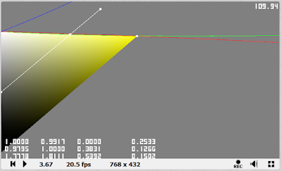
The left image show the precision error for calculating the cusp point at hue 232.58 degree
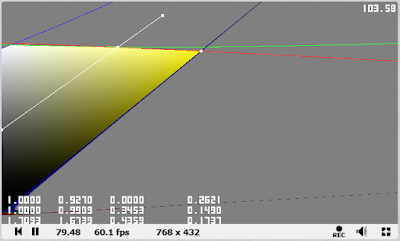
The right image can calculate the cusp point correctly with < 1 degree hue difference from left image


Solving RGB=1 clipping line with 2 curves only

From previous post, we know that the upper clipping line of the valid gamut "triangle" is the line with Red/Green/Blue value = 1, and at most 2 clipping lines are used:

This yellow hue use 2 upper clipping lines (red and green lines)

In the updated Shadertoy demo, the upper "triangle" clipping method is changed to use 2 clipping lines depending on the r_dir / g_dir / b_dir (computed during max saturation).

Originally clipping code using all 3 lines
updated clipping code using 2 lines depending on hue

And during my implementation, I accidentally found that when performing gamut clipping for ACEScg color space, I forgot to calculate the chromatic adaptation due to different white point (Oklab uses D65 while ACEScg uses roughly D60), all 3 upper clipping lines need to be used:

All 3 upper clipping lines are used due to chromatic adaption bug

Result

Now, let's see how gamut clipping looks in rendered image. All 5 gamut clipping methods from Björn Ottosson's blog are implemented:

  1. Keep lightness constant, only compress chroma (Chroma clipped)
  2. Projection towards a single point, hue independent (L0=0.5 projection)
  3. Projection towards a single point, hue dependent (L0=Lcusp projection)
  4. Adaptive L0, hue independent (Adaptive L0=0.5)
  5. Adaptive L0, hue dependent (Adaptive L0=Lcusp)

Let's start with a night scene, the clipping effect is most noticeable in the blue curtain and a slight change in the green curtain:

Without gamut clipping
Chroma clipped
Out of gamut pixels
L0=0.5 projection
Adaptive L0=0.5, α=5.0
Adaptive L0=0.5, α=0.05
L0=Lcusp projection
Adaptive L0=Lcusp, α=5.0
Adaptive L0=Lcusp, α=0.05

Then the following test scenes all use a light with saturated color (e.g. red color with (1, 0, 0) in Rec2020) to generate out of gamut color. With a saturated magenta colored light, gamut clipping can do a pretty good job at showing the details for the out of gamut area (e.g. around the lion face) 

Without gamut clipping
Chroma clipped
Out of gamut pixels
L0=0.5 projection
Adaptive L0=0.5, α=5.0
Adaptive L0=0.5, α=0.05
L0=Lcusp projection
Adaptive L0=Lcusp, α=5.0
Adaptive L0=Lcusp, α=0.05

Changing to a saturated green light, different clipping methods will change the perceived lighting, especially using projection towards a single point method.

Without gamut clipping
Chroma clipped
Out of gamut pixels
L0=0.5 projection
Adaptive L0=0.5, α=5.0
Adaptive L0=0.5, α=0.05
L0=Lcusp projection
Adaptive L0=Lcusp, α=5.0
Adaptive L0=Lcusp, α=0.05

With a saturated red light, gamut clipping can greatly reduce the orange/yellow hue shift. This reminds me the presentation: "HDR in Call of Duty" and "HDR color grading and display in Frostbite", which talked about some of the VFX (e.g. fire/explosion) may relies on such hue shift. I don't know whether it is good or not, but gamut clipping may at least give a closer look between sRGB display and HDR display...

Without gamut clipping
Chroma clipped
Out of gamut pixels
L0=0.5 projection
Adaptive L0=0.5, α=5.0
Adaptive L0=0.5, α=0.05
L0=Lcusp projection
Adaptive L0=Lcusp, α=5.0
Adaptive L0=Lcusp, α=0.05

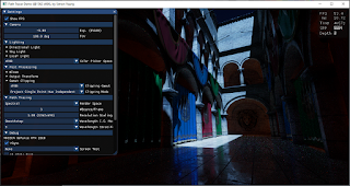
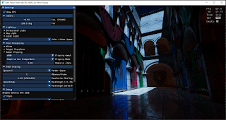
As gamut clipping can reduce hue shift for the saturated red color, I was wondering whether it can fix hue shift with blue colored light (in sRGB) showing purple which described in DXR Path Tracer post before. Unfortunately, gamut clipping can't fix this... I guess this may need to be fixed earlier in the pipeline (e.g. in tone mapper or use other gamut mapping method)...

Without gamut clipping
With gamut clipping
Out of gamut pixels

Lastly, a scene with not much saturated color, but overexposure is tested. Gamut clipping doesn't change the image much: 

Without gamut clipping
With gamut clipping
Out of gamut pixels

Conclusion

In this post, an analytical solution is provided to perform gamut clipping for different gamut other than sRGB. Also different gamut clipping method are tested. "Compress chroma only" looks quite decent, while projection towards single point may change the perceived lightness of the image (depends on the lighting set up), while the adaptive method using small alpha value (e.g. 0.05) will behave similar to compress chroma only method, while with large alpha (e.g. >5.0), it will behave similar to the projection towards single point method. The demo can be downloaded to play around with different gamut clipping method. Note that the demo relies on a saturated light color to generate out of gamut color and all the albedo textures are in sRGB (due to the texture spectral up-sampling method only support sRGB while light color is using a different spectral up-sampling method). Also, my demo performs the gamut clipping before blending with UI as all the UI are in sRGB color space, in the future, I may need to think about whether the UI should be gamut clipped if wide color are used...

References

[1] https://bottosson.github.io/posts/gamutclipping/

[2] https://www.ea.com/frostbite/news/high-dynamic-range-color-grading-and-display-in-frostbite

[3] https://research.activision.com/publications/archives/hdr-in-call-of-duty