Introduction
In this generation of computer graphics, global illumination (GI) is an important technique which calculate indirect lighting within a scene. Photon mapping is one of the GI technique using particle tracing to compute images in offline rendering. Photon mapping is an easy to implement technique, so I choose to learn it and my target is to bake light map storing indirect diffuse lighting information using the photon map. Photon mapping consists of 2 passes: photon map pass and render pass, which will be described below.
Photon Map Pass
In this pass, photons will be casted into the scene from the position of light source. Each photon store packet of energy. When photon hits a surface of the scene, the photon will either be reflected (either diffusely or specularly), transmitted or absorbed, which is determined by Russian roulette.
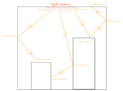 |
| Photons are traced in the scene to simulate the light transportation |
This hit event represents the incoming energy of that surface and will be stored in a
k-d tree (known as photon map) for looking up in the render pass. Each hit event would store the photon energy, the incoming direction and the hit position.
However, it is more convenient to store radiance than storing energy in photon because when using punctual light source(e.g. point light), it is hard to compute the energy emits given the light source radiance. So I use the method described in
Physically Based Rendering, a weight of radiance is stored in each photon:
When a photon hits a surface, the probability of being reflected in a new random direction used in Russian roulette is:
This probability equation is chosen because photon will have a higher chance of being reflected if it is brighter. If the photon is reflected, its radiance will be updated to:
And the photon will continue to trace in the newly reflected direction.
Render pass
In render pass, the direct and indirect lighting is computed separately. The direction lighting is computed using ray tracing.
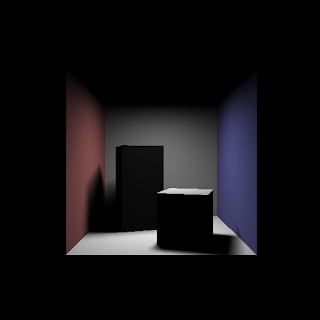 |
| Direct light only |
The indirect lighting is computed by sampling from the photon map. When calculating the indirect lighting in a given position(in this case, the shading pixel), we can locate N nearby photons in photon map to estimate the incoming radiance using
kernel density estimation. A
kernel function need to satisfy the conditions:
I use the Simpson's kernel(also known as Silverman's second order kernel) suggested in the book Physically Based Rendering:
Then the density can be computed using kernel estimator for N samples within a distance d (i.e. the distance of the photon that is the most far away in the N samples):
Then the reflected radiance at the shading position can be computed with:
However, the result showing some circular artifact:
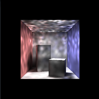 |
Using the photon map directly for indirect diffuse
light would show artifact |
To tackle this problem, either increase the number of photon to a very high number, or we can perform a final gather step. In the final gather step, we shoot a number of final gather rays from the pixel that we are shading in random direction over the hemisphere of the shading point.
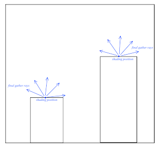 |
| Final gather rays are casted from every shading position |
When final gather ray hit another surface, then the photon map is queried just like before and the reflected radiance from this surface will be the incoming radiance of the shading pixel. Using Monte Carlo integration, the reflected radiance at the shading pixel can be calculated by sampling the final gather rays. Here is the final result:
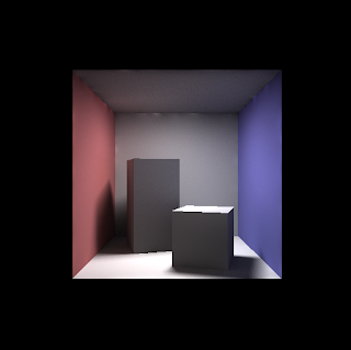 |
| Direct light + Indirect light, with final gather |
|
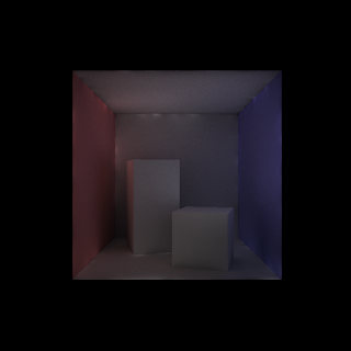 |
| Indirect light only, with final gather |
|
Conclusion
In this post, the steps to implement photon map is briefly described. It is a 2 passes approach with the photon map pass building a photon map as kd-tree representing the indirect lighting data and the render pass use the photon map to compute the final image. In next part, I will describe how to make use of the photon map to bake light map for real time application.
References


